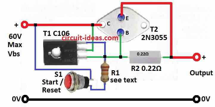
Fuse Circuit Diagrams Test the electronic fuse by applying power and pressing the start/reset button S1. Verify that the circuit activates and deactivates as expected when the current exceeds or falls below the threshold. Note: By following these steps and referring to the schematic diagram provided, you can build the described DC electronic fuse.

In some experiments, electronic circuits require fuse protection. The circuit may be difficult. Because, often short, to change the fuse every time. , Thus wasting time. To solve this problem, we Build this electronic fuse limiter circuit, so instead of plain fuses. By it can cut off the current immediately. When a short circuit as well.
Electronic Fuse Circuit for Power Supply Circuit Diagram
Fuses, positive temperature coefficient (PTC) resistors, and active circuit protection are a few of the protection devices with varied capabilities and drawbacks. Fuses are traditionally considered as protection devices used to isolate overload or short-circuit faults from the main system. Although these devices
Creating an electronic fuse circuit diagram entails understanding the necessities of the circuit, including how much current you're expecting to pass through it. This will help you determine the size of the fuse you need to install — too small of a fuse and it won't provide enough protection to the circuit; too large and it might prevent Electronic Fuse Schematic Diagram . Current fuse can be set to the maximum output current (about 10 mA) up to the maximum allowable current of the transistor T1 (BUZ11 - 20A). the fuse is power supply of +5 V with integrated stabilizer 7805, +5 V voltage reference voltage and therefore stability is important to determine the accuracy of the
PDF Basics of eFuses (Rev. A) Circuit Diagram
The complete circuit diagram for an electronic fuse circuit is shown below. As shown in the circuit, it involves only few circuits and hence it is easy to construct and implement into our designs. Here the circuit is constructed to monitor the operating current of a motor (LOAD), which operates on 12V. You can replace the load with any circuit
