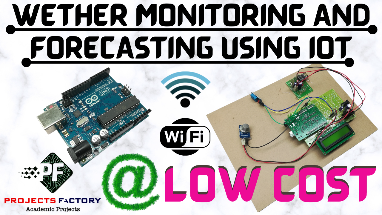
Weather Monitoring And Forecasting Using IOT Circuit Diagram The proposed model is used to develop the accurate weather information in real-time, making it an ideal solution for individuals and organizations looking to monitor local weather conditions. By

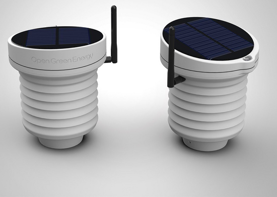
3.3 Solar Power Components. If you've opted for solar power, gather the necessary components for your solar charging system. This may include solar panels, charge controllers, batteries, and wiring. Ensure that your solar panel provides sufficient power to charge your batteries and operate your weather station effectively.
(PDF) Developing a Sustainable IoT Circuit Diagram
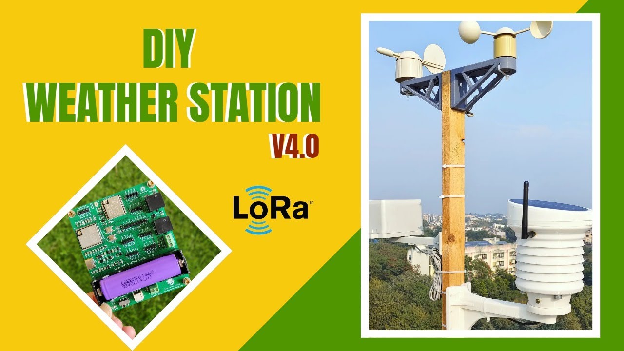
Optional: Solar Panel. A great feature of the CubeCell board is the ability to connect a small solar panel; the board has onboard battery management and will charge the battery from the energy provided by the solar panel. In my installation, I used this panel, which is 110x60mm panel. I find this, coupled with a 650mAh battery, to provide more

Learn how to build a weather monitoring system using IoT. Get live weather updates and forecasts. Build your weather station now! Wrong menu selected Smarter Power Solutions: Solar-powered weather stations use low-power IoT devices to solve power issues in remote areas. As a result, they work reliably even when getting electricity is hard.
Powered Weather Station with LoRa Circuit Diagram
The power system in Weather Pi consists of four parts: Two Solar Panels. One 6600Ah LiPo Battery. SunAirPlus Solar Power Controller, Pi Power Supply; and Data Gathering system. USB PowerControl board for Pi Power Control. We are using 2 3.4W Solar Panels from Voltaic Systems.